At a Glance
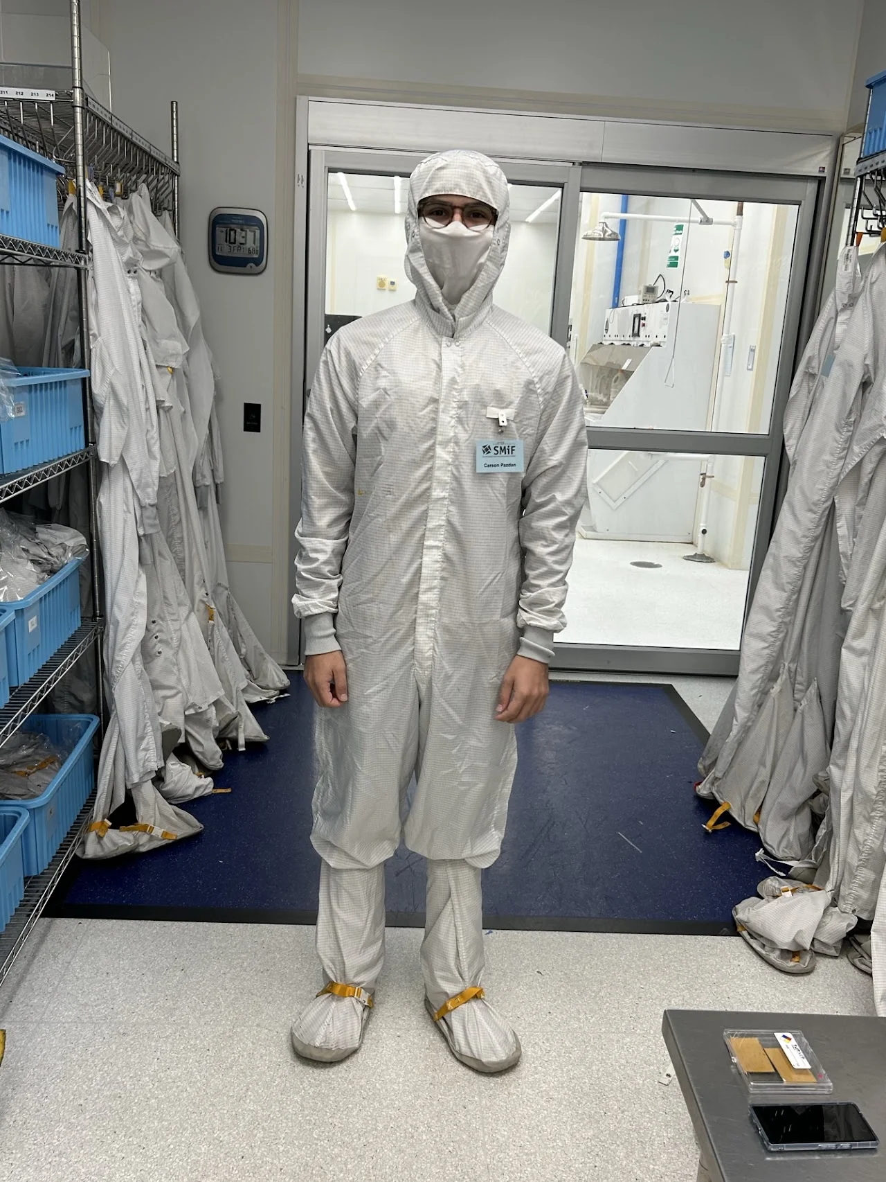
- Lab: The Viventi Lab at Duke designs wireless, implantable sEEG (stereoelectroencephalography) electrodes that work with existing stereotactic equipment and can better localize seizures.
- My role: Undergraduate research assistant. I worked on two fabrication problems for the lab's liquid crystal polymer (LCP) electrodes: sealing them (encapsulation) and shaping them (helical coiling). I designed the fixtures and test methods for both, with a graduate student mentor in an advisory role.
- Tools: Duke SMiF cleanroom, heat press, CT imaging, SolidWorks/Onshape, 3D printing, waterjet cutting.
1. LCP Encapsulation
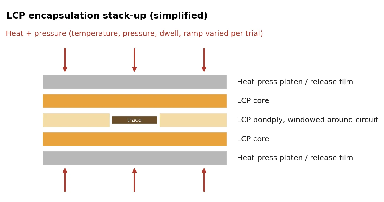
LCP is a biocompatible thermoplastic that absorbs far less water than conventional implant polymers, which makes it a strong candidate for long-term implants. The challenge is bonding layers of LCP core and bondply around the electrode's metal traces without voids or delamination.
What I Did
- Ran a structured series of heat-press trials, varying stack-up (core vs. bondply layering), temperature, pressure, dwell time, and ramped heating and cooling, and logged nominal vs. actual plate temperatures on every run.
- Prepared PDMS-coated carrier slides and patterned test circuits in the cleanroom, and encapsulated LEDs and magnesium foil as test articles.
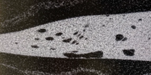
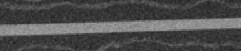
- Used cross-sections and CT scans to find voids a visual check missed, then changed the stack-up and press parameters to close them.
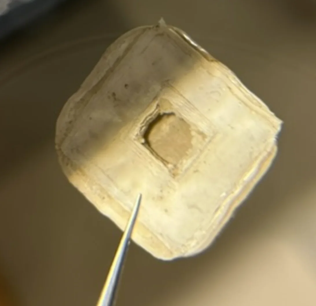
- Isolated a root cause with a controlled adhesion test: identical stacks bonded into a single monolayer without a trace but failed with a copper trace in the center, showing the bondply was bonding to the copper instead of the core. That pointed the next round toward more bondply-to-core contact area.
- Result: Optimization eliminated the voids visible on CT. I helped set up the lab's saline soak testing before leaving for the summer; the lab's later results for the optimized protocol showed under 0.006% mass loss over 30 days.
LCP Alignment Jig
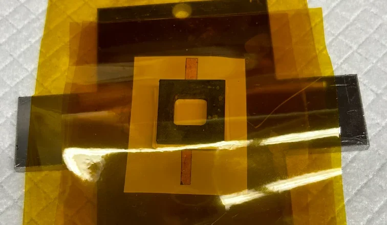
To stack 20–50 layers of LCP and bondply and keep them aligned through the heat press, I designed a clamping plate-jig that goes into the press with the material. The plates have wings so they can be pulled out hot with tongs. Parts were designed in SolidWorks, 3D printed, and waterjet-cut from metal.
2. Helical Electrode Coiling
Coiling the electrode's lead into a helix makes it more flexible, so the implant can move with the brain instead of against it, which should reduce tissue damage and immune response. The lab's coils were wound by hand, which made pitch inconsistent. My goal was a mechanically assisted process that wraps a thin LCP ribbon around a removable rod at a constant, adjustable pitch, works with different rod diameters, and is repeatable enough to scale toward production.
Iteration 1: Horizontal Winder
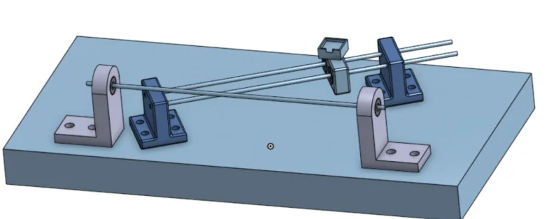
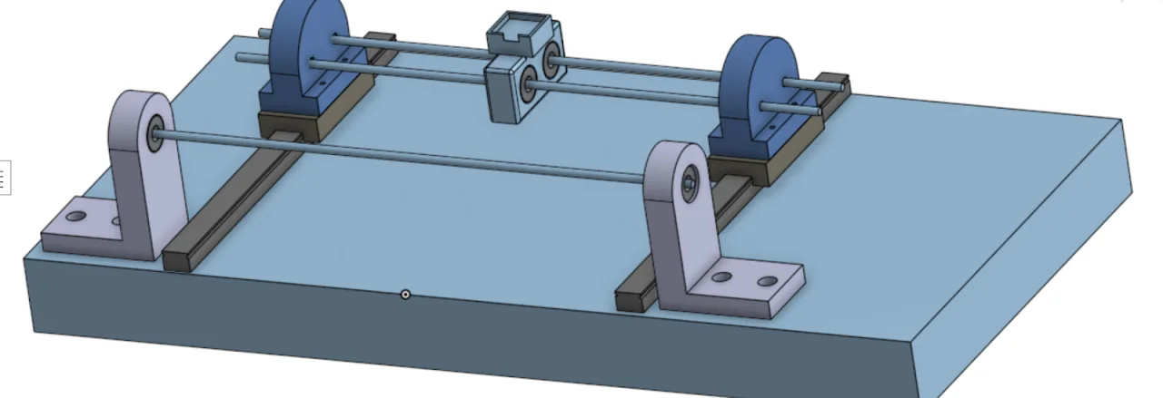
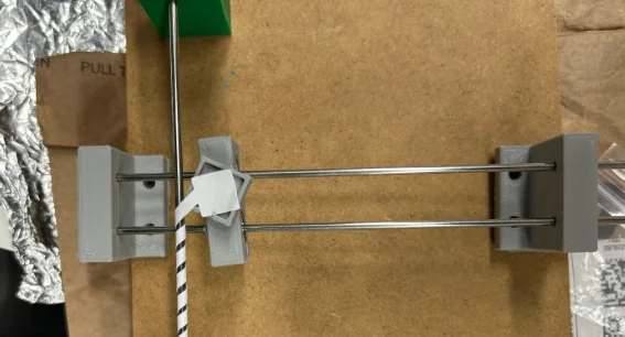
Inspired by fishing-reel line winders, the first design fed the ribbon from a carriage on rails while the rod turned. Working through the geometry, I found that an angled approach changes pitch as the carriage moves, and that moving the feed perpendicular to the rod at a fixed starting angle holds pitch constant. The hand-operated prototype wound paper leads with adjustable pitch, but it couldn't keep steady tension on real LCP, and 3D-printed parts couldn't hold the tolerances needed at this scale.
Iteration 2: Inclined, Gravity-tensioned Winder
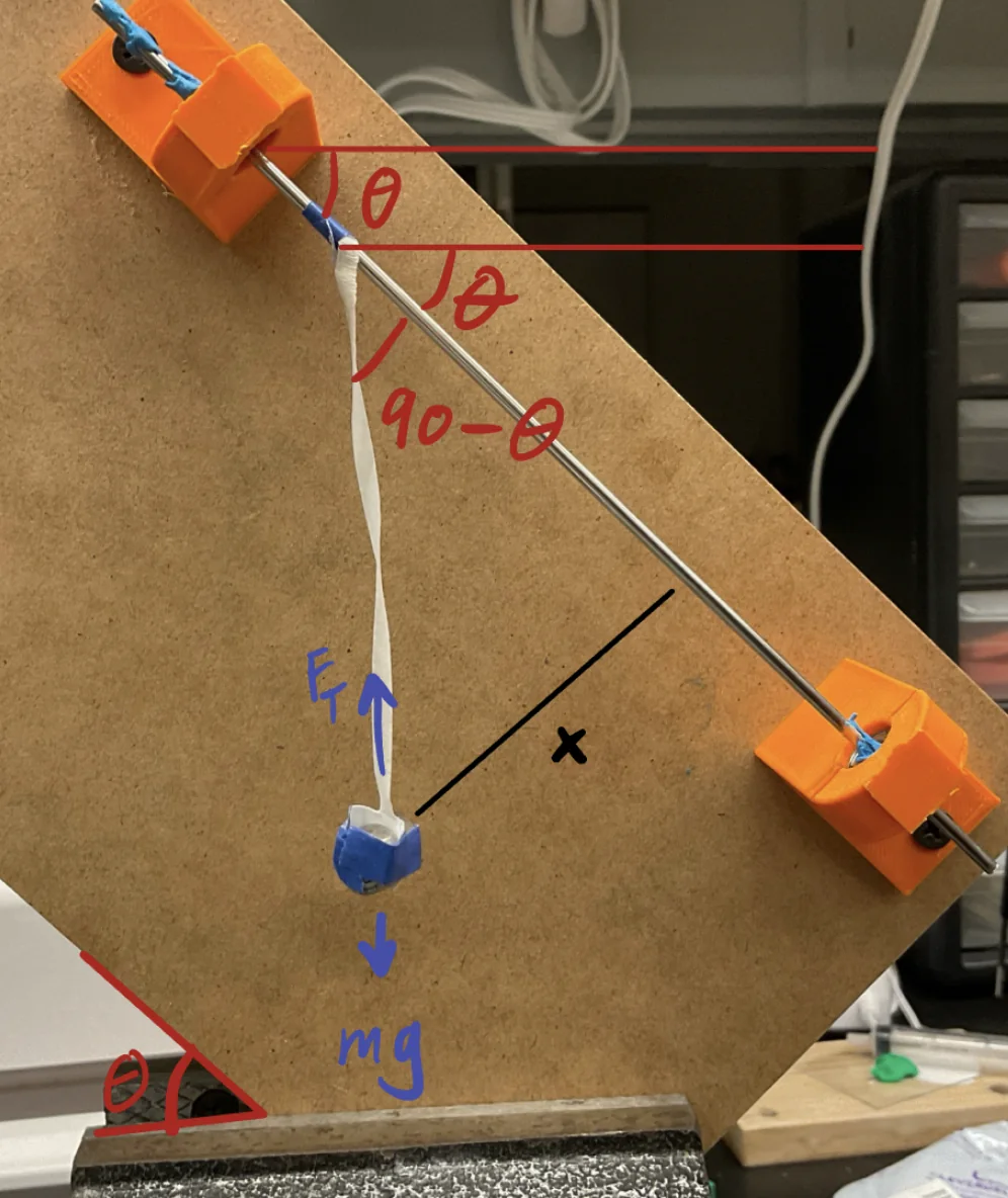
I reoriented the design so gravity does the work. The rod sits on an inclined board, and a weight hangs from the ribbon. The board angle sets the ribbon's approach angle (its complement), so angles can be marked on the board once instead of re-measured every run, and the weight keeps tension constant as the coil grows. Testing showed tension was the limiting factor: without it, the coil slid back toward its starting point.
Along the way I evaluated rod materials (tungsten, carbon fiber, high-speed steel, PTFE tubing) down to 0.83 mm, where the rod became too flexible to tension. I also tested adhesives for the initial attachment (epoxy and super glue failed on silicone) and wrote a repeatable attachment protocol using heat-shrink and a medical-grade adhesive.
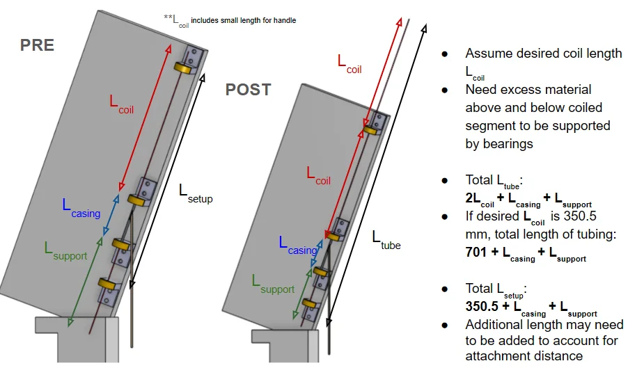
Result: On the inclined prototype with 1 mm OD tubing, 100 µm LCP (2.52 mm wide), and a 20° approach, 14 measured turns averaged 5.55 ± 0.28 mm pitch, about 5% variation. That's consistent, though below the roughly 8.6 mm the geometry predicted, which pointed to slack in the ribbon at shallow angles. At 45°, coiling was much easier to observe and control, and pitch was semi-consistent near the expected value.

Handoff: I handed the project off at this stage, and another lab member carried the inclined design through to finished electrodes.
What I Took Away
Most of the hard problems here weren't in the CAD. They were in tension, attachment, and material behavior at a scale where 3D-printer tolerances run out. Both projects came down to designing a test that isolates one variable, whether that was a copper trace in an adhesion test or pitch versus approach angle.
Lab Notebooks
Next project
Bluetooth-Enabled Pacemaker · VVI demand pacing with BLE telemetry