At a Glance
- What: A non-invasive wearable that records single-channel EEG from behind the ear, streams it wirelessly to a machine learning model, and alerts the user's phone when it classifies a pre-ictal (pre-seizure) or ictal state.
- My role: System integration lead. I owned the processing-unit hardware (rebiasing and power circuitry, custom PCB layout, battery monitoring), the back-mounted enclosure, and the firmware and cloud connection that tie acquisition to the ML model.
- Outcome: Working end-to-end prototype, a full Design History File, and a finalist for the People's Choice Award at Duke's senior design showcase.
The Problem
About a quarter of people with epilepsy have drug-resistant (refractory) epilepsy, where medication gives little or no seizure control. The danger is in the unpredictability: refractory epilepsy is associated with a 4–7x higher mortality rate, and 43% of patients report serious seizure-related injuries. We need a way to reliably predict tonic-clonic seizures to notify persons with drug-resistant epilepsy so that they may move to a safe space, enhancing safety and quality of life.
System Architecture
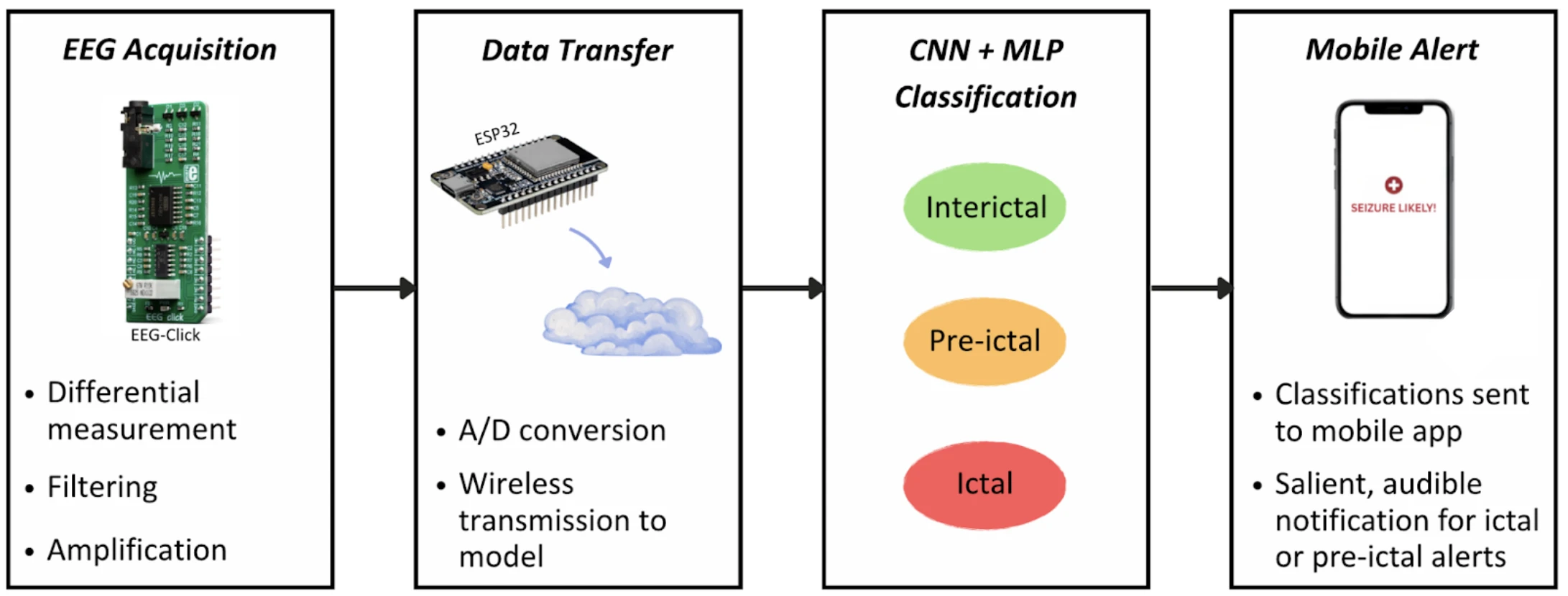
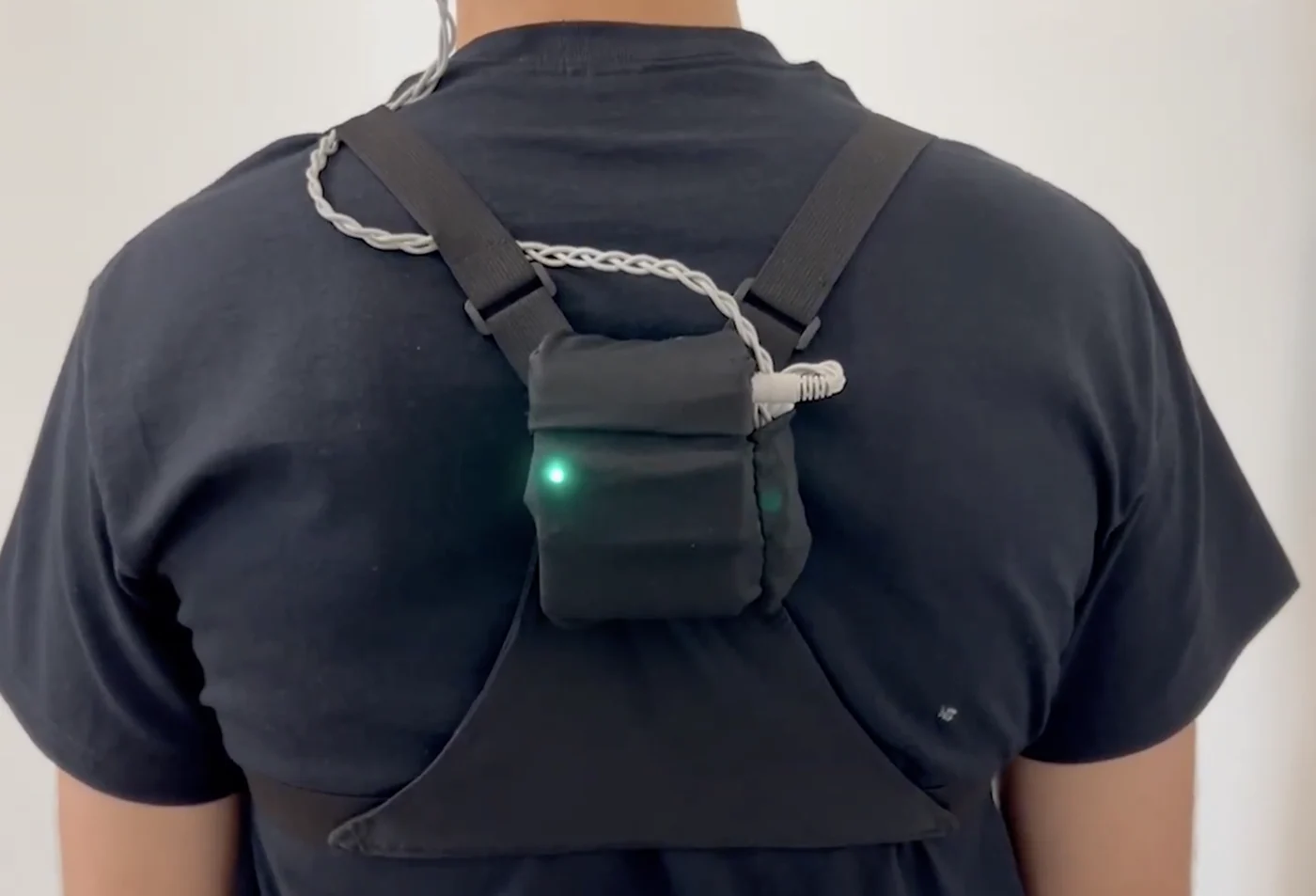
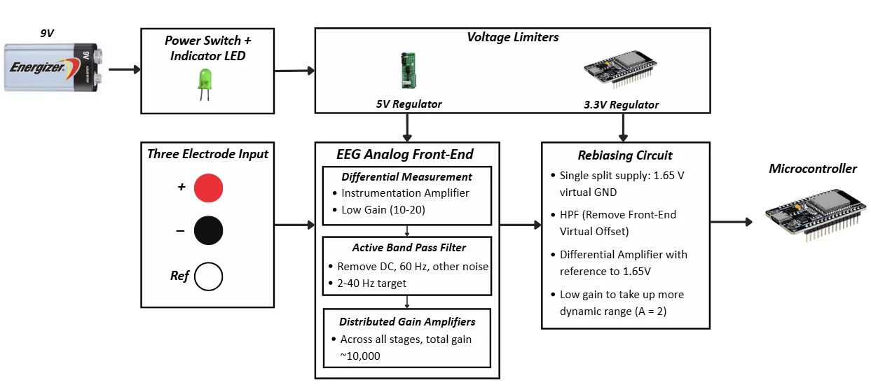
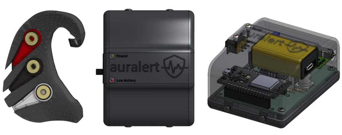
The system has three physical pieces: a flexible behind-the-ear electrode holder, a back-mounted processing unit, and an adjustable harness that holds the unit and manages the cable. Inside the processing unit, a commercial EEG-Click module handles differential measurement, band-pass filtering, and high gain. A rebiasing circuit shifts that signal onto a 1.65 V virtual ground so it fits the ESP32's 0–3.3 V ADC range, adds a 1.6 Hz high-pass stage to strip the front end's DC offset, and applies a small gain to use more of the ADC's dynamic range. The ESP32 streams the digitized EEG to a server running the classifier, and classifications come back to an iPhone app.
Key Integration Decisions
- One battery, multiple rails. A single rechargeable 9V (USB-C) feeds a 5V regulator for the EEG-Click and a 3.3V regulator for logic, so the whole unit runs from one cell the user charges.
- ESP32 over a smaller microcontroller. It was larger than we wanted, but it was the only option in budget with both the processing headroom and the wireless link we needed.
- Make vs. buy on acquisition. We designed and built our own EEG front end first (below), then evaluated a second lab-designed board and the commercial EEG-Click. The EEG-Click gave the most consistent signal, so we built the final system around it and put our design effort into integration instead.
- Interface specs across teams. I relayed the acquisition circuit's input/output voltage ranges to the ML side so the model expected the same signal scale the hardware actually produced.
Hardware
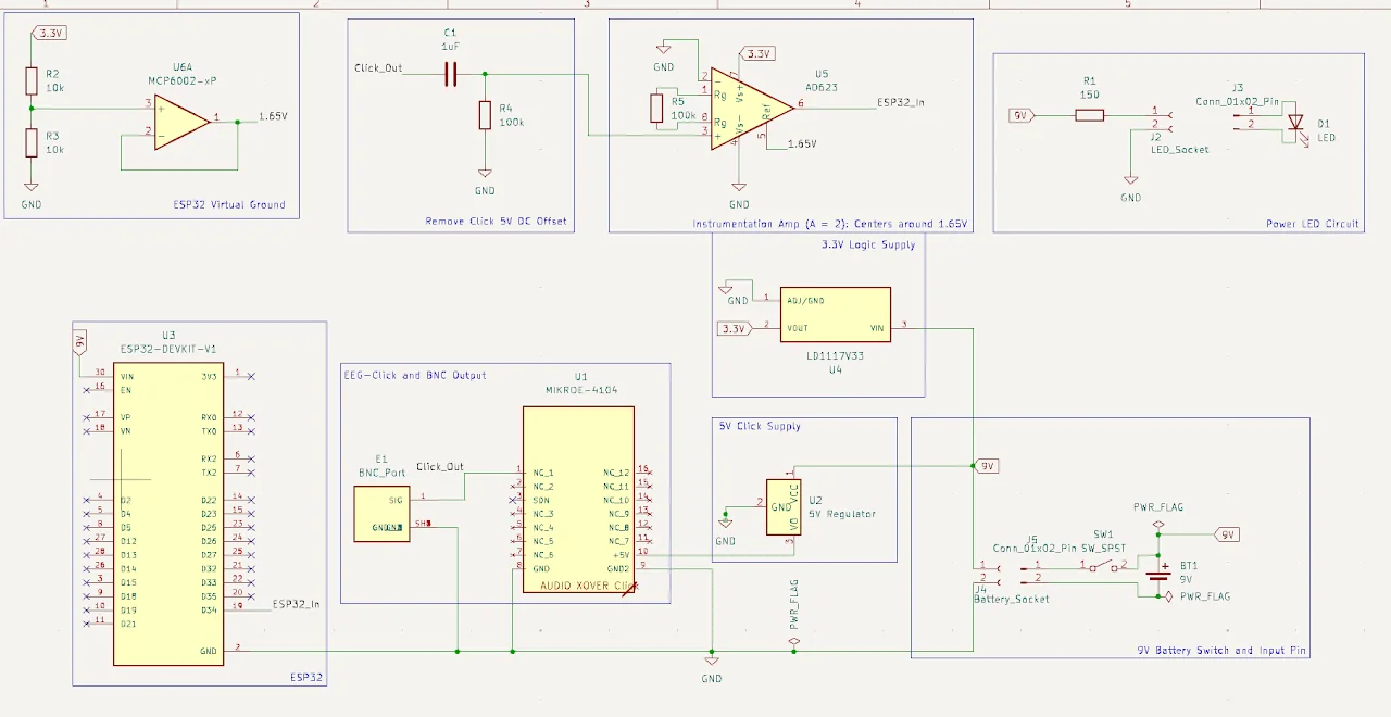
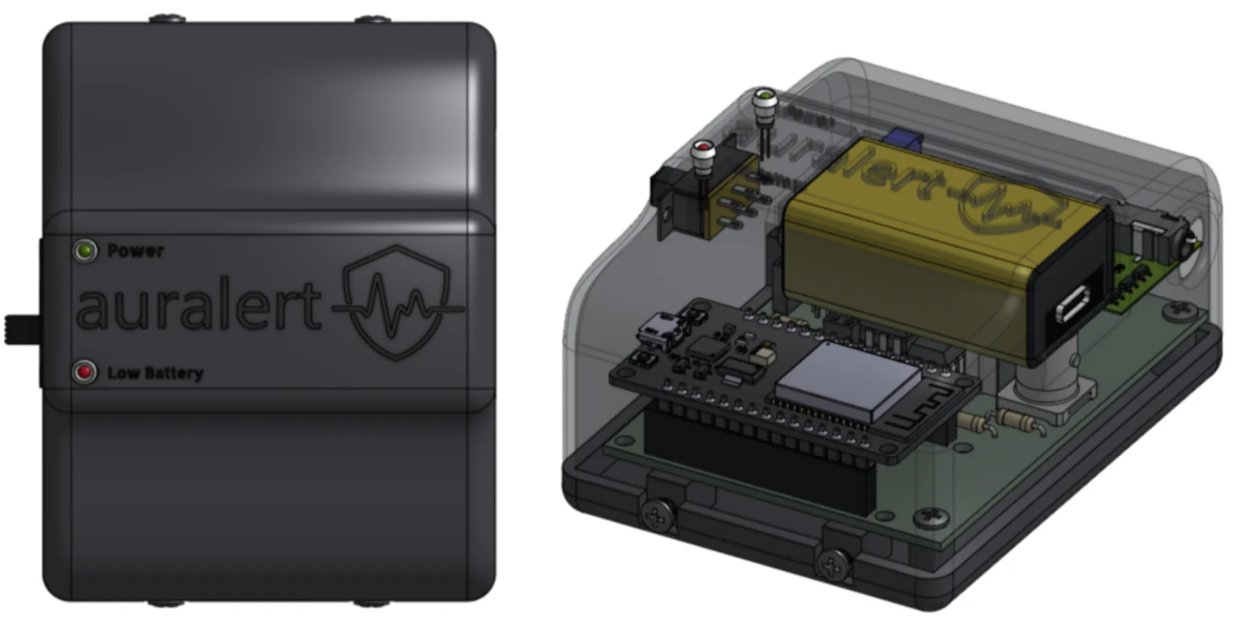
The final PCB carries the rebiasing stage, both regulators, the battery switch, the power LED, and a low-battery indicator that lights when the 9V drops below 7V (a safety margin above the 5V the system needs). The enclosure was printed in Formlabs Tough 2000 resin for drop resistance, with bosses for heat-set inserts to fix the PCB and lid. I redesigned it shorter and longer late in the project so it fits in a pocket on the harness.
Earlier Iteration: Custom EEG Front End
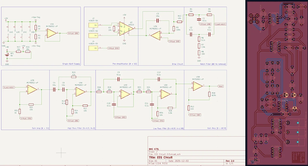
Our first design was a fully custom analog front end: instrumentation amplifier pre-amp (gain 11), a common-mode drive circuit, a 60 Hz Twin-T notch, a Sallen-Key high-pass (1.5 Hz) and 4th-order low-pass (40.8 Hz), and distributed gain stages. Bench testing with Bode plots showed the filters tracked their theoretical responses, and I laid out and soldered the PCB. On the board, noise kept us from recording EEG reliably, which is what pushed the make-vs-buy decision above.
Wearable Design
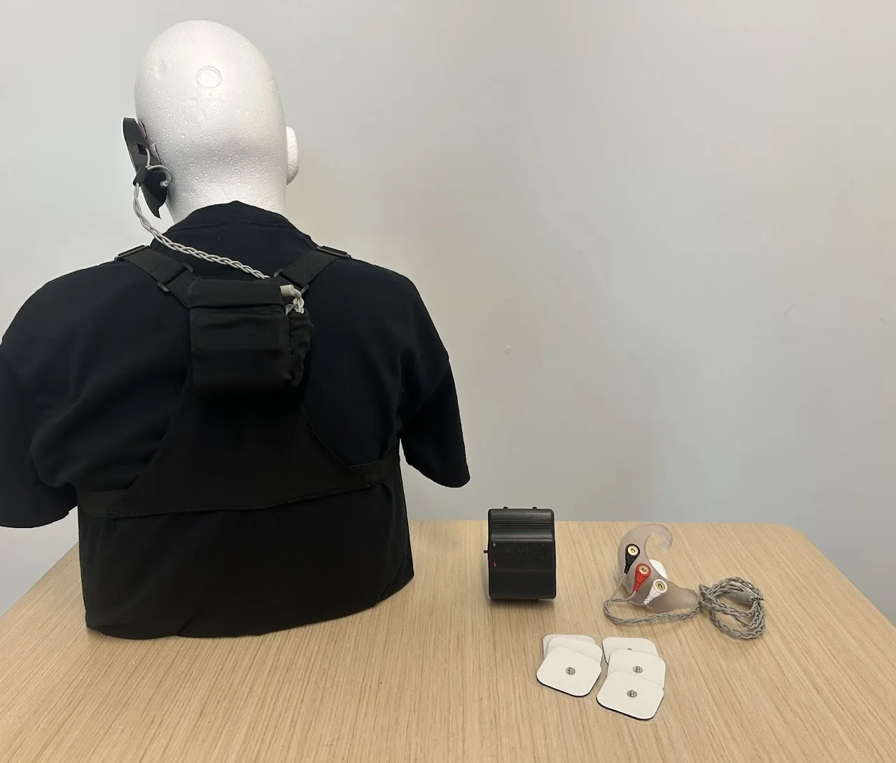
The behind-the-ear holder keeps three disposable snap electrodes flush against the head. After PLA was too rigid and silicone casting lost critical features, the final part was printed in BioMed Elastic 50A resin. The processing unit moved from the waist to the upper back, and the three electrode wires were braided into one cord that stores in a pouch on the harness.
Risk Analysis (FMEA)
We scored 15 failure modes across five design blocks by severity, occurrence, and detection (RPN = S × O × D), then made design changes for the top five.
| Design block | Failure | Effect | S | O | D | RPN | Change implemented |
|---|---|---|---|---|---|---|---|
| EEG PCB | Wire fracture | Added noise, loss of signal | 7 | 7 | 8 | 392 | Moved the enclosure from waist to back to shorten the cable, braided the three leads into one cord, added a storage pouch |
| Microcontroller | Insufficient battery power | ESP32 can't send or receive | 8 | 5 | 8 | 320 | Rechargeable 9V with USB-C and a low-battery indicator (triggers below 7V) |
| Wearable | Device damaged during a seizure | Broken PCB, fractured wires, loose electrodes | 8 | 6 | 6 | 288 | Enclosure printed in drop-resistant Tough 2000 resin |
| Wearable | Electrodes dry out | Higher impedance, worse signal | 7 | 8 | 4 | 224 | Switched from reusable to single-use electrodes after testing showed degradation after one use |
| Notification | Alert not noticeable enough | Seizure without warning | 7 | 4 | 8 | 224 | Replaced a haptic motor and buzzer with an iPhone app that sends an Emergency Bypass (Amber-Alert-style) notification |
| EEG PCB | Movement artifacts | False predictions | 7 | 5 | 5 | 175 | Planned: filtering (see V&V) |
| ML | False positive | Undue stress | 6 | 9 | 3 | 162 | Planned: model refinement |
| EEG PCB | Insufficient battery power | EEG-Click can't measure | 8 | 9 | 2 | 144 | Shared battery indicator |
| Wearable | Electrodes decouple from head | Noise or signal loss | 7 | 7 | 2 | 98 | Planned: close-fit holder |
| ML | False negative | No warning, loss of trust | 10 | 9 | 1 | 90 | Planned: model refinement |
| Wearable | Earpiece doesn't fit | Can't wear device | 6 | 5 | 2 | 60 | Planned: flexible material / sizes |
| Notification | Bluetooth drop-off | No alerts | 7 | 3 | 2 | 42 | Planned: flag and reconnect |
| Wearable | Cable pulls loose from holder | No EEG recorded | 9 | 4 | 1 | 36 | Planned: flush electrode seats |
| Microcontroller | Wireless disconnect | No predictions | 7 | 5 | 1 | 35 | Planned: flag and reconnect |
| Wearable | Wires too short | Can't place electrodes | 6 | 5 | 1 | 30 | Planned: adjustable cable |
The notification change is the clearest example of the FMEA doing its job. A buzzer seemed reasonable until we scored it against a real failure scenario and realized it probably wouldn't reliably alert someone at the onset of a seizure.
Verification & Validation
Without access to epilepsy patients, we split validation into three questions, each with a written protocol and success criteria in the DHF.
1. Can the Device Acquire EEG?
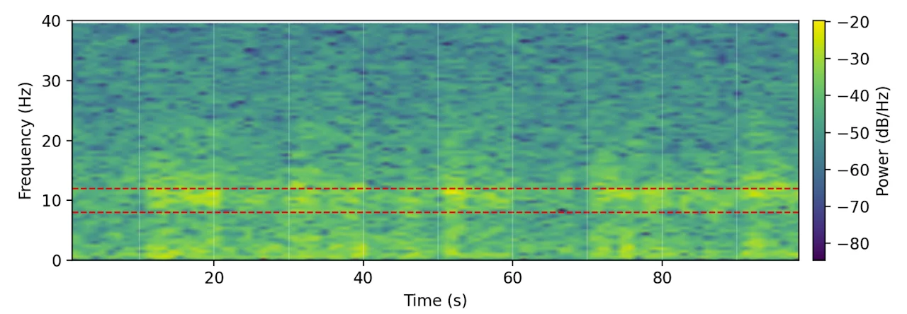
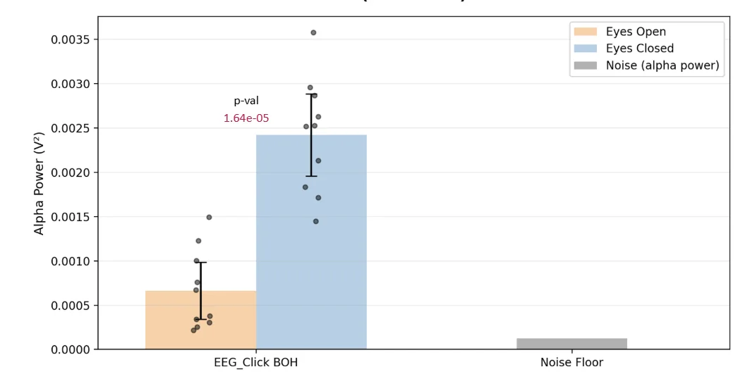
Alpha-band power (8–12 Hz) over the occipital lobe reliably rises when the eyes close. We recorded 10 alternating eyes-open and eyes-closed windows and found a significant increase in alpha power with eyes closed, well above the system's noise floor.
2. Can the Model Classify Epileptic States?
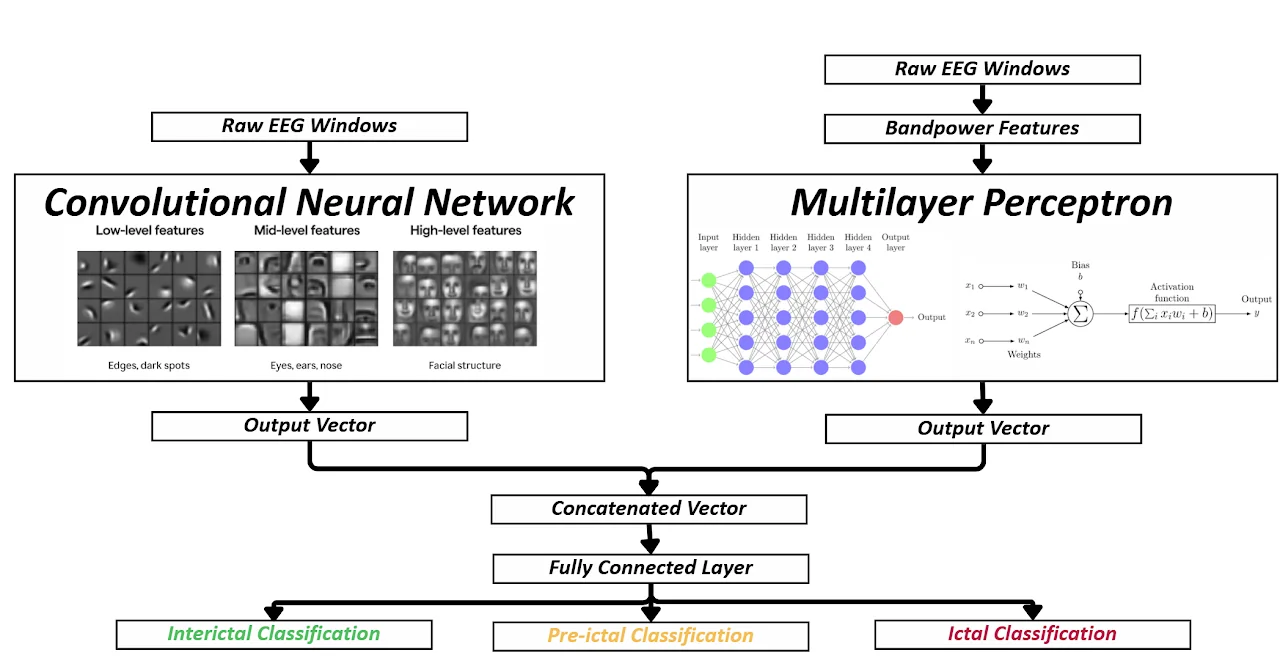
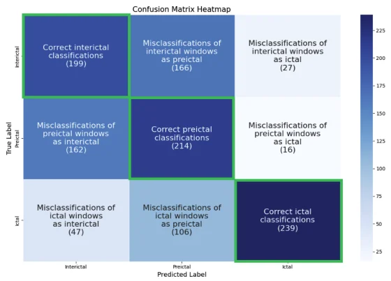
Our ML teammate built a dual-input model that classifies 5-second windows as interictal, pre-ictal, or ictal, trained on single-channel scalp EEG from 22 patients in the CHB-MIT database with an 80/20 held-out split. It separates ictal windows reasonably well but often confuses pre-ictal with interictal, the hardest distinction in seizure prediction and the main target for future work.
3. Does the Full System Work on a Real Person?
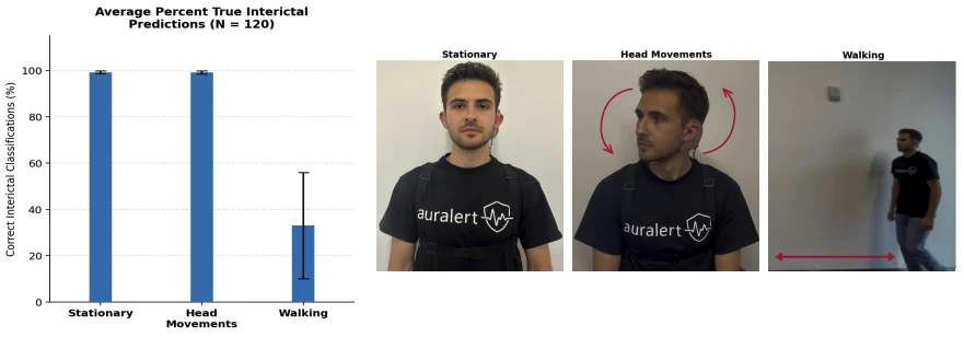
We tested the complete wearable on four non-epileptic subjects, who should always be classified as interictal, across three 5-minute conditions: sitting still, talking and moving the head, and walking. Averaged across all three conditions, the system classified 76.5% of windows correctly as interictal, with accuracy near 100% when subjects were stationary or moving their heads. Walking was the weak point: each step produced a motion artifact the model read as an ictal spike.
Chasing the movement-artifact problem. I traced it through the signal chain. The EEG-Click's own high-pass cutoff is only 0.25 Hz, so I added a 1.6 Hz analog high-pass in the rebiasing stage. A steeper digital filter (1–2 Hz) did remove the artifacts, but it also stripped features the model depended on and pushed every prediction to interictal, so we rejected it. We then tested whether mechanical fixes (tightening the harness, stowing the cable) changed 1–2 Hz power during walking; they didn't significantly. Along the way, we found a new failure mode: with electrodes disconnected, the noise floor saturates the ESP32's analog input and can overheat the chip.
What I'd Do Next
- Clinical testing with epilepsy patients, to evaluate the system during real seizure events.
- A stronger model: more training data and larger, temporal architectures to separate pre-ictal from interictal.
- Motion robustness: handling movement artifacts in hardware from the start. An accelerometer reference channel is where I'd begin, so the system can tell a footstep from a seizure spike.
- Caregiver alerts: notifying a caregiver or clinician automatically on an ictal classification.
Next project
Pediatric Crash-Test Neck · Finite element redesign in LS-DYNA